
티스토리 뷰
Raspberry Pi 2 & 3 Pin Mappings
출처: https://docs.microsoft.com/en-us/windows/iot-core/learn-about-hardware/pinmappings/pinmappingsrpi
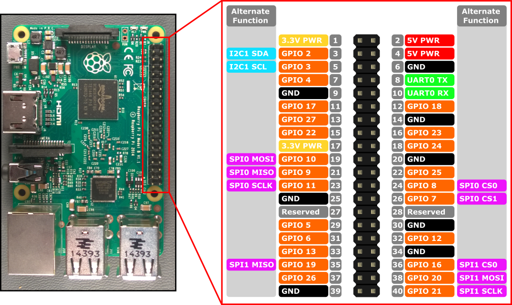
Raspberry Pi 2 및 Raspberry Pi 3의 하드웨어 인터페이스는 보드의 40 핀 헤더 J8을 통해 노출됩니다. 기능에는 다음이 포함됩니다.
- 24x - GPIO pins
- 1x - Serial UARTs (RPi3 only includes mini UART)
- 2x - SPI bus
- 1x - I2C bus
- 2x - 5V power pins
- 2x - 3.3V power pins
- 8x - Ground pins
| GPIO# | Power-on Pull | Alternate Functions | Header Pin |
|---|---|---|---|
| 2 | PullUp | I2C1 SDA | 3 |
| 3 | PullUp | I2C1 SCL | 5 |
| 4 | PullUp | 7 | |
| 5 | PullUp | 29 | |
| 6 | PullUp | 31 | |
| 7 | PullUp | SPI0 CS1 | 26 |
| 8 | PullUp | SPI0 CS0 | 24 |
| 9 | PullDown | SPI0 MISO | 21 |
| 10 | PullDown | SPI0 MOSI | 19 |
| 11 | PullDown | SPI0 SCLK | 23 |
| 12 | PullDown | 32 | |
| 13 | PullDown | 33 | |
| 16 | PullDown | SPI1 CS0 | 36 |
| 17 | PullDown | 11 | |
| 18 | PullDown | 12 | |
| 19 | PullDown | SPI1 MISO | 35 |
| 20 | PullDown | SPI1 MOSI | 38 |
| 21 | PullDown | SPI1 SCLK | 40 |
| 22 | PullDown | 15 | |
| 23 | PullDown | 16 | |
| 24 | PullDown | 18 | |
| 25 | PullDown | 22 | |
| 26 | PullDown | 37 | |
| 27 | PullDown | 13 | |
| 35* | PullUp | Red Power LED | |
| 47* | PullUp | Green Activity LED |
* = Raspberry Pi 2에만 해당됩니다. GPIO 35 & 47은 Raspberry Pi 3에서는 사용할 수 없습니다.
GPIO 샘플
예를 들어, 다음 코드는 GPIO 5를 출력으로 열고 디지털 '1'을 핀에 씁니다.
using Windows.Devices.Gpio;

public void GPIO()
{
    // Get the default GPIO controller on the system
    GpioController gpio = GpioController.GetDefault();
    if (gpio == null)
        return; // GPIO not available on this system

    // Open GPIO 5
    using (GpioPin pin = gpio.OpenPin(5))
    {
        // Latch HIGH value first. This ensures a default value when the pin is set as output
        pin.Write(GpioPinValue.High);

        // Set the IO direction as output
        pin.SetDriveMode(GpioPinDriveMode.Output);

    } // Close pin - will revert to its power-on state
}
핀을 열면 전원이 켜지며 풀 저항이 포함될 수 있습니다. 풀 저항을 분리하고 하이 임피던스 입력을 얻으려면 드라이브 모드를 GpioPinDriveMode.Input으로 설정하십시오.
pin.SetDriveMode(GpioPinDriveMode.Input);
핀이 닫히면 전원이 켜지는 상태로 되돌아갑니다.
핀 다중화(Pin Muxing)
일부 GPIO 핀은 여러 기능을 수행 할 수 있습니다. 기본적으로 핀은 GPIO 입력으로 구성됩니다. I2cDevice.FromIdAsync () 또는 SpiDevice.FromIdAsync ()를 호출하여 대체 함수를 열면 함수에서 필요로하는 핀이 자동으로 올바른 함수로 전환 ( "다중화")됩니다. I2cDevice.Dispose () 또는 SpiDevice.Dispose ()를 호출하여 장치를 닫으면 핀이 기본 기능으로 돌아갑니다. 한 번에 2 개의 다른 기능에 핀을 사용하려고하면, 충돌하는 기능을 열려고 할 때 예외가 발생합니다. 예를 들어,
var controller = GpioController.GetDefault();
var gpio2 = controller.OpenPin(2);      // open GPIO2, shared with I2C1 SDA

var dis = await DeviceInformation.FindAllAsync(I2cDevice.GetDeviceSelector());
var i2cDevice = await I2cDevice.FromIdAsync(dis[0].Id, new I2cConnectionSettings(0x55)); // exception thrown because GPIO2 is open

gpio2.Dispose(); // close GPIO2
var i2cDevice = await I2cDevice.FromIdAsync(dis[0].Id, new I2cConnectionSettings(0x55)); // succeeds because gpio2 is now available

var gpio2 = controller.OpenPin(2); // throws exception because GPIO2 is in use as SDA1

i2cDevice.Dispose(); // release I2C device
var gpio2 = controller.OpenPin(2); // succeeds now that GPIO2 is available
직렬 UART(Serial UART)
RPi2 / 3에는 하나의 직렬 UART가 있습니다 : UART0
- Pin 8 - UART0 TX
- Pin 10 - UART0 RX
using Windows.Storage.Streams;
using Windows.Devices.Enumeration;
using Windows.Devices.SerialCommunication;

public async void Serial()
{
    string aqs = SerialDevice.GetDeviceSelector("UART0");                   /* Find the selector string for the serial device   */
    var dis = await DeviceInformation.FindAllAsync(aqs);                    /* Find the serial device with our selector string  */
    SerialDevice SerialPort = await SerialDevice.FromIdAsync(dis[0].Id);    /* Create an serial device with our selected device */

    /* Configure serial settings */
    SerialPort.WriteTimeout = TimeSpan.FromMilliseconds(1000);
    SerialPort.ReadTimeout = TimeSpan.FromMilliseconds(1000);
    SerialPort.BaudRate = 9600;                                             /* mini UART: only standard baudrates */
    SerialPort.Parity = SerialParity.None;                                  /* mini UART: no parities */
    SerialPort.StopBits = SerialStopBitCount.One;                           /* mini UART: 1 stop bit */
    SerialPort.DataBits = 8;

    /* Write a string out over serial */
    string txBuffer = "Hello Serial";
    DataWriter dataWriter = new DataWriter();
    dataWriter.WriteString(txBuffer);
    uint bytesWritten = await SerialPort.OutputStream.WriteAsync(dataWriter.DetachBuffer());

    /* Read data in from the serial port */
    const uint maxReadLength = 1024;
    DataReader dataReader = new DataReader(SerialPort.InputStream);
    uint bytesToRead = await dataReader.LoadAsync(maxReadLength);
    string rxBuffer = dataReader.ReadString(bytesToRead);
}
직렬 UART 코드를 실행하려면 UWP 프로젝트의 Package.appxmanifest 파일에 다음 기능을 추가해야합니다.
Visual Studio 2017에는 직렬 통신 기능에 영향을주는 매니페스트 디자이너 (appxmanifest 파일의 시각적 편집기)에 알려진 버그가 있습니다. appxmanifest가 직렬 통신 기능을 추가하면 appxmanifest를 디자이너로 수정하면 appxmanifest가 손상됩니다 (Device xml 하위가 손실 됨). appxmanifest를 마우스 오른쪽 버튼으로 클릭하고 컨텍스트 메뉴에서 코드보기를 선택하여 appxmanifest를 손으로 편집하여이 문제를 해결할 수 있습니다.
  <Capabilities>
    <DeviceCapability Name="serialcommunication">
      <Device Id="any">
        <Function Type="name:serialPort" />
      </Device>
    </DeviceCapability>
  </Capabilities>
I2C Bus
| Signal Name | Header Pin Number | Gpio Number |
|---|---|---|
| SDA | 3 | 2 |
| SCL | 5 | 3 |
아래 예제는 I2C1을 초기화하고 주소 0x40의 I2C 장치에 데이터를 씁니다.
using Windows.Devices.Enumeration;
using Windows.Devices.I2c;

public async void I2C()
{
    // 0x40 is the I2C device address
    var settings = new I2cConnectionSettings(0x40);
    // FastMode = 400KHz
    settings.BusSpeed = I2cBusSpeed.FastMode;

    // Create an I2cDevice with the specified I2C settings
    var controller = await I2cController.GetDefaultAsync();

    using (I2cDevice device = controller.GetDevice(settings))
    {
        byte[] writeBuf = { 0x01, 0x02, 0x03, 0x04 };
        device.Write(writeBuf);
    }
}
SPI Bus
SPI0
Signal Name Header Pin Number Gpio Number MOSI 19 10 MISO 21 9 SCLK 23 11 CS0 24 8 CS1 26 7
SPI1
Signal Name Header Pin Number Gpio Number MOSI 38 20 MISO 35 19 SCLK 40 21 CS0 36 16
SPI 샘플
칩 선택 0을 사용하여 버스 SPI0에서 SPI 쓰기를 수행하는 방법의 예는 다음과 같습니다.
using Windows.Devices.Enumeration;
using Windows.Devices.Spi;

public async void SPI()
{
    // Use chip select line CS0
    var settings = new SpiConnectionSettings(0);
    // Set clock to 10MHz
    settings.ClockFrequency = 10000000;

    // Get a selector string that will return our wanted SPI controller
    string aqs = SpiDevice.GetDeviceSelector("SPI0");

    // Find the SPI bus controller devices with our selector string
    var dis = await DeviceInformation.FindAllAsync(aqs);

    // Create an SpiDevice with our selected bus controller and Spi settings
    using (SpiDevice device = await SpiDevice.FromIdAsync(dis[0].Id, settings))
    {
        byte[] writeBuf = { 0x01, 0x02, 0x03, 0x04 };
        device.Write(writeBuf);
    }
}
출처; https://docs.microsoft.com/en-us/windows/iot-core/learn-about-hardware/pinmappings/pinmappingsrpi
'프로그래밍 > C#' 카테고리의 다른 글
| 맥에 MySQL 설치하기 (0) | 2018.09.20 |
|---|---|
| MinnowBoard Max Pin Mappings (0) | 2018.08.23 |
| 드래곤 보드 핀 매핑(Dragonboard Pin Mappings) (0) | 2018.08.23 |
| 하드웨어 호환성 목록 (0) | 2018.08.23 |
| 라즈베라파이 window iot led점멸 첫번째 프로그램 만들기 (0) | 2018.08.07 |