
티스토리 뷰
드래곤 보드 핀 매핑(Dragonboard Pin Mappings)
출처: https://docs.microsoft.com/en-us/windows/iot-core/learn-about-hardware/pinmappings/pinmappingsdb
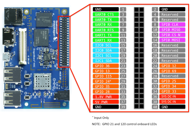
드래곤 보드의 하드웨어 인터페이스는 보드의 40 핀 헤더를 통해 노출됩니다. 기능에는 다음이 포함됩니다.
- 11x - GPIO pins
- 2x - Serial UARTs
- 1x - SPI bus
- 2x - I2C bus
- 1x - 5V power pin
- 1x - 1.8V power pin
- 4x - Ground pins
드래곤 보드는 모든 IO 핀에서 1.8V 로직 레벨을 사용합니다.
GPIO 핀
이 장치에서 사용할 수있는 GPIO를 살펴 보겠습니다.
GPIO 핀 테이블
다음 GPIO 핀은 API를 통해 액세스 할 수 있습니다.
| GPIO# | Header Pin |
|---|---|
| 36 | 23 |
| 12 | 24 |
| 13 | 25 |
| 69 | 26 |
| 115 | 27 |
| 24 | 29 |
| 25 | 30 |
| 35 | 31 |
| 34 | 32 |
| 28 | 33 |
| 33 | 34 |
| 21 | User LED 1 |
| 120 | User LED 2 |
예를 들어, 다음 코드는 GPIO 35를 출력으로 열고 디지털 '1'을 핀에 씁니다.
using Windows.Devices.Gpio;

public void GPIO()
{
    GpioController Controller = GpioController.GetDefault(); /* Get the default GPIO controller on the system */

    GpioPin Pin = Controller.OpenPin(35);       /* Open GPIO 35                      */
    Pin.SetDriveMode(GpioPinDriveMode.Output);  /* Set the IO direction as output   */
    Pin.Write(GpioPinValue.High);               /* Output a digital '1'             */
}
GPIO 문제
출력이 GPIO 24에서 작동하지 않습니다. 입력이 정상적으로 작동합니다.
핀은 부팅시 InputPullDown으로 구성되지만 처음 열 때 입력 (부동)으로 변경됩니다.
닫을 때 핀이 기본 상태로 되돌아 가지 않습니다.
인터럽트가 다중 핀에서 인 에이블 될 때 스퓨리어스 인터럽트가 보일 수있다.
직렬 UART
드래곤 보드 UART0과 UART1에는 두 개의 Serial UART가 있습니다.
UART0에는 표준 UART0 TX 및 UART0 RX 라인과 흐름 제어 신호 UART0 CTS 및 UART0 RTS가 있습니다.
핀 5 - UART0 TX
핀 7 - UART0 RX
핀 3 - UART0 CTS
핀 9 - UART0 RTS
UART1은 UART1 TX 및 UART1 RX 라인 만 포함합니다.
핀 11 - UART1 TX
핀 13 - UART1 RX
아래의 예는 UART1을 초기화하고 쓰기를 수행 한 다음 읽기를 수행합니다.
using Windows.Storage.Streams;
using Windows.Devices.Enumeration;
using Windows.Devices.SerialCommunication;

public async void Serial()
{
    string aqs = SerialDevice.GetDeviceSelector("UART1");                   /* Find the selector string for the serial device   */
    var dis = await DeviceInformation.FindAllAsync(aqs);                    /* Find the serial device with our selector string  */
    SerialDevice SerialPort = await SerialDevice.FromIdAsync(dis[0].Id);    /* Create an serial device with our selected device */

    /* Configure serial settings */
    SerialPort.WriteTimeout = TimeSpan.FromMilliseconds(1000);
    SerialPort.ReadTimeout = TimeSpan.FromMilliseconds(1000);
    SerialPort.BaudRate = 9600;
    SerialPort.Parity = SerialParity.None;
    SerialPort.StopBits = SerialStopBitCount.One;
    SerialPort.DataBits = 8;

    /* Write a string out over serial */
    string txBuffer = "Hello Serial";
    DataWriter dataWriter = new DataWriter();
    dataWriter.WriteString(txBuffer);
    uint bytesWritten = await SerialPort.OutputStream.WriteAsync(dataWriter.DetachBuffer());

    /* Read data in from the serial port */
    const uint maxReadLength = 1024;
    DataReader dataReader = new DataReader(SerialPort.InputStream);
    uint bytesToRead = await dataReader.LoadAsync(maxReadLength);
    string rxBuffer = dataReader.ReadString(bytesToRead);
}
참고: Visual Studio 2017에는 직렬 통신 기능에 영향을주는 매니페스트 디자이너 (appxmanifest 파일의 시각적 편집기)에 알려진 버그가 있습니다. appxmanifest가 직렬 통신 기능을 추가하면 appxmanifest를 디자이너로 수정하면 appxmanifest가 손상됩니다 (Device xml 하위가 손실 됨). appxmanifest를 마우스 오른쪽 버튼으로 클릭하고 컨텍스트 메뉴에서 코드보기를 선택하여 appxmanifest를 직접 편집하여이 문제를 해결할 수 있습니다.
직렬 UART 코드를 실행하려면 UWP 프로젝트의 Package.appxmanifest 파일에 다음 기능을 추가해야합니다.
  <Capabilities>
    <DeviceCapability Name="serialcommunication">
      <Device Id="any">
        <Function Type="name:serialPort" />
      </Device>
    </DeviceCapability>
  </Capabilities>
I2C 버스
이 장치에서 사용할 수있는 I2C 버스를 살펴 보겠습니다.
I2C 핀
I2C0은 두 개의 라인 SDA와 SCL로 핀 헤더에 노출
핀 17 - I2C0 SDA
핀 15 - I2C0 SCL
I2C1은 두 개의 라인 SDA와 SCL로 핀 헤더에 노출
핀 21 - I2C1 SDA
핀 19 - I2C1 SCL
I2C 샘플
아래 예제는 I2C0을 초기화하고 주소 0x40의 I2C 장치에 데이터를 씁니다.
using Windows.Devices.Enumeration;
using Windows.Devices.I2c;

public async void I2C()
{
    // 0x40 is the I2C device address
    var settings = new I2cConnectionSettings(0x40);
    // FastMode = 400KHz
    settings.BusSpeed = I2cBusSpeed.FastMode;

    // Get a selector string that will return our wanted I2C controller
    string aqs = I2cDevice.GetDeviceSelector("I2C0");

    // Find the I2C bus controller devices with our selector string
    var dis = await DeviceInformation.FindAllAsync(aqs);

    // Create an I2cDevice with our selected bus controller and I2C settings
    using (I2cDevice device = await I2cDevice.FromIdAsync(dis[0].Id, settings))
    {
        byte[] writeBuf = { 0x01, 0x02, 0x03, 0x04 };
        device.Write(writeBuf);
    }
}
SPI 버스
이 장치에서 사용할 수있는 SPI 버스를 살펴 보겠습니다.
SPI 핀
DB에는 하나의 SPI 컨트롤러 SPI0이 있습니다.
핀 10 - SPI0 MISO
핀 14 - SPI0 MOSI
핀 8 - SPI0 SCLK
핀 12 - SPI0 CS0
SPI 문제
SPI 클럭은 4.8mhz로 고정되어 있습니다. 요청한 SPI 클럭은 무시됩니다.
SPI 샘플
버스 SPI0에서 SPI 쓰기를 수행하는 방법에 대한 예는 다음과 같습니다.
using Windows.Devices.Enumeration;
using Windows.Devices.Spi;

public async void SPI()
{
    // Use chip select line CS0
    var settings = new SpiConnectionSettings(0);

    // Create an SpiDevice with the specified Spi settings
    var controller = await SpiController.GetDefaultAsync();

    using (SpiDevice device = controller.GetDevice(settings))
    {
        byte[] writeBuf = { 0x01, 0x02, 0x03, 0x04 };
        device.Write(writeBuf);
    }
}'프로그래밍 > C#' 카테고리의 다른 글
| 맥에 MySQL 설치하기 (0) | 2018.09.20 |
|---|---|
| MinnowBoard Max Pin Mappings (0) | 2018.08.23 |
| Raspberry Pi 2 & 3 Pin Mappings (0) | 2018.08.23 |
| 하드웨어 호환성 목록 (0) | 2018.08.23 |
| 라즈베라파이 window iot led점멸 첫번째 프로그램 만들기 (0) | 2018.08.07 |